An ultrasensitive laser interferometer to measure the motion of a mirror to within a few picometers
The laser interferometer was our first project that started with an empty lab in the Fall of 2011. The outstanding Ed Lynch (`13) worked extensively to design and build much of the optics, the electronics, and wrote almost all the control software.
Brief description and layout
Our interferometer is built around a 1550 nm DFB laser that provides roughly 1 mW of output power. The laser light is guided into a single mode fiber and then into a coupler. One port of the coupler picks off 1% of the light and directs it towards the experiment inside an ultrahigh vacuum chamber. A small aspheric lens focuses the light onto a thin flexible silicon mirror and also collects a small portion of the reflected light. The free end of the fiber and the flexible silicon mirror form a Fabry-Perot cavity and small changes in the position of the mirror produce phase shifts that are detected using an amplified photodetector. A small piezoelectric disk is epoxied to the back end of the mirror. This disk is used to make small adjustments to the cavity length and also to control the amplitude of the mirror vibrations. The disk is left grounded when the mirror vibrations are monitored passively.
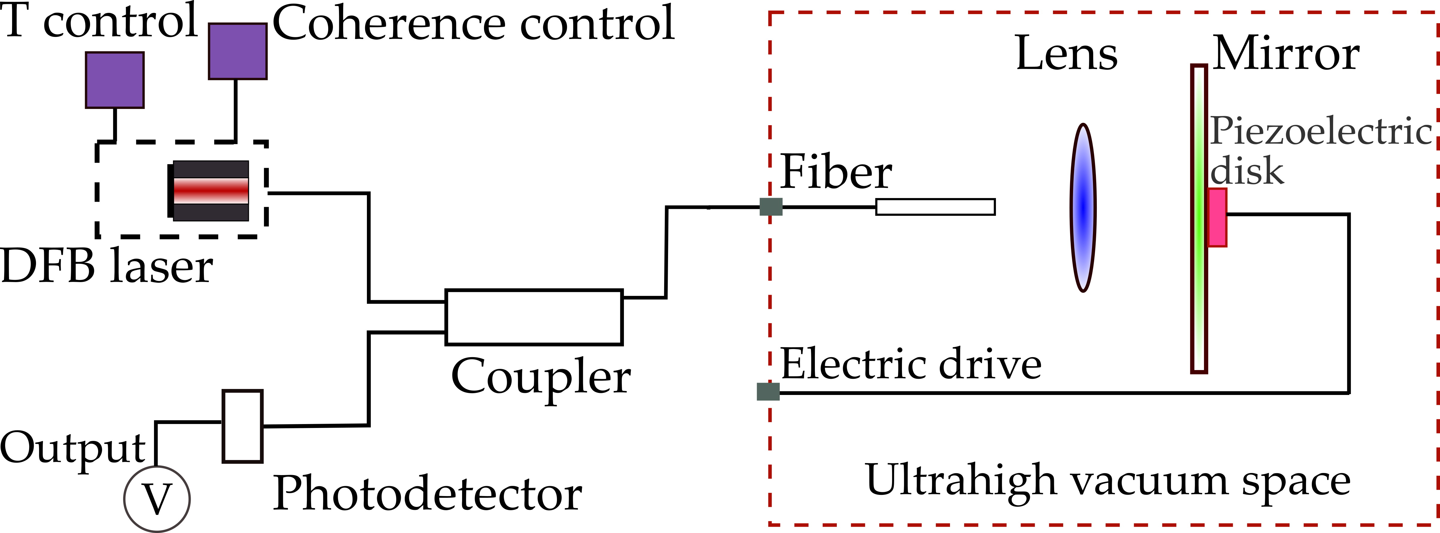
Figure 1: Layout of the interferometer. The 1550 nm DFB laser module is fiber coupled into an ultrahigh vacuum chamber. The interferometer cavity of length ~ 3 mm is formed between the free end of the fiber and a thin silicon mirror. The interferometer output is available as a voltage on the amplified photoreceiver. The laser is temperature controlled to slightly tweak its wavelength and the mirror is mounted on a small piezoelectric disk to slightly tweak the cavity length. Two feedback loops keep the interferometer centered at its operating point and the mirror vibrating with constant amplitude respectively.
The laser is temperature controlled so we can tune its wavelength inside a feedback loop and our choice of the DFB laser ensures the tuning is very clean and free of mode hops. For increased stability, we reduce the coherence length of the laser by injecting about 10 dBm of 300 MHz rf power into the laser drive current using a bias tee. Under these conditions, the interferometer is remarkably stable and with the feedback loop enabled runs unattended continuously for months at a time.
Ultrahigh vacuum chamber
The components inside the ultrahigh vacuum chamber are shown in Figure 2 below. Laser light is guided inside the chamber using a single mode fiber that passes into the vacuum space using a home built epoxy-less vacuum feedthrough. This vacuum feedthrough utilizes a soft deformable teflon ferrule that fits inside a compresssion fitting on a 2-3/4" CF flange. The fiber passes through a 10 mil clear hole drilled into the teflon ferrule after which the compression fitting is tightened. We obtain excellent vacuum with this arrangement and our unbaked chamber base pressure easily reaches ~ 10-6 Torr within a few hours.
The free end of the fiber is cut using an ultrasonic cleaver for a sharp glass-air interface which significantly improves the performance and stability of the interferometer. The freshly cleaved end is held in place on a stainless steel sleeve and focused onto a silicon mirror placed roughly 3 mm away. A piezoelectric disk is mounted on the back end of the mirror for amplitude control of the mirror vibrations. A z-positioner is also shown and is part of a separate project but is not required for the operation of the interferometer.
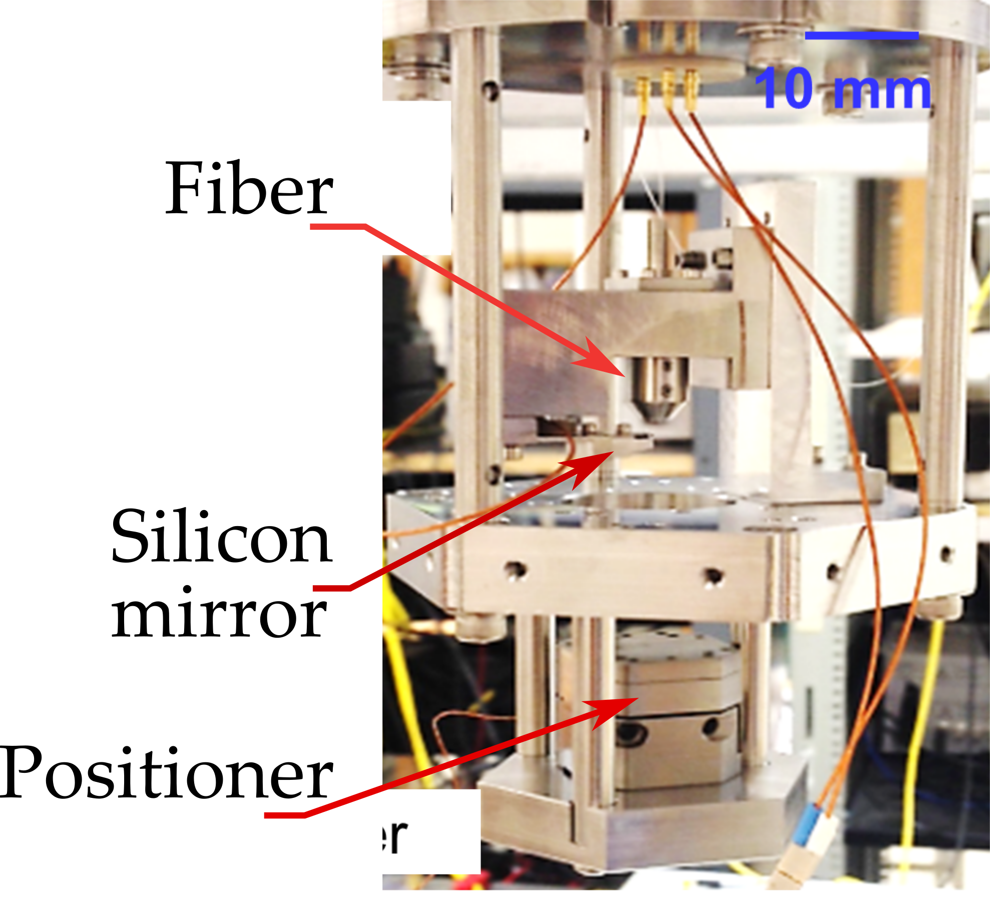 Figure 2: Details of the interferometer components inside the ultrahigh vacuum chamber. The components are mounted onto a custom machined 6" CF flange. Shown is the fiber which is held in place inside a stainless steel sleeve, the silicon mirror which is clamped to a ledge, a piezoelectric disk affixed to the rear of the mirror mount, and the z positioner which is part of a separate project. Kapton coated vacuum compatible wires provide electrical inputs to the piezoelectric disk and the z-positioner.
Electronics
The interferometer output is available as a dc coupled voltage V and this is used in two different ways. In one scheme, the dc coupled output is continuously monitored within a feedback loop implemented in software. This is shown in Figure 3 (a) below. This feedback loop corrects for slow drifts of the interferometer from its most sensitive operating point by slightly adjusting the temperature of the DFB laser. The output wavelength changes by roughly 0.25 nm per C and this slight temperature coefficient is sufficient to keep the interferometer operating at its correct working point. With this feedback loop enabled, the interferometer runs unattended continuously at its correct operating point.
The output voltage is also used to drive a second feedback loop implemented as an analog PI controller. This is shown in Figure 3 (b). The purpose of this second feedback loop is to keep the silicon mirror vibrating with a constant amplitude. The required amplitude is set with an analog potentiometer, and the PI feedback controller adjusts the drive to a piezoelectric disk glued to the silicon mirror to keep the vibration amplitude constant. We are easily able to to control the drive amplitude from 1 nm to almost 100 nm peak. With both feedback loops enabled, the mirror maintains constant amplitude oscillations.
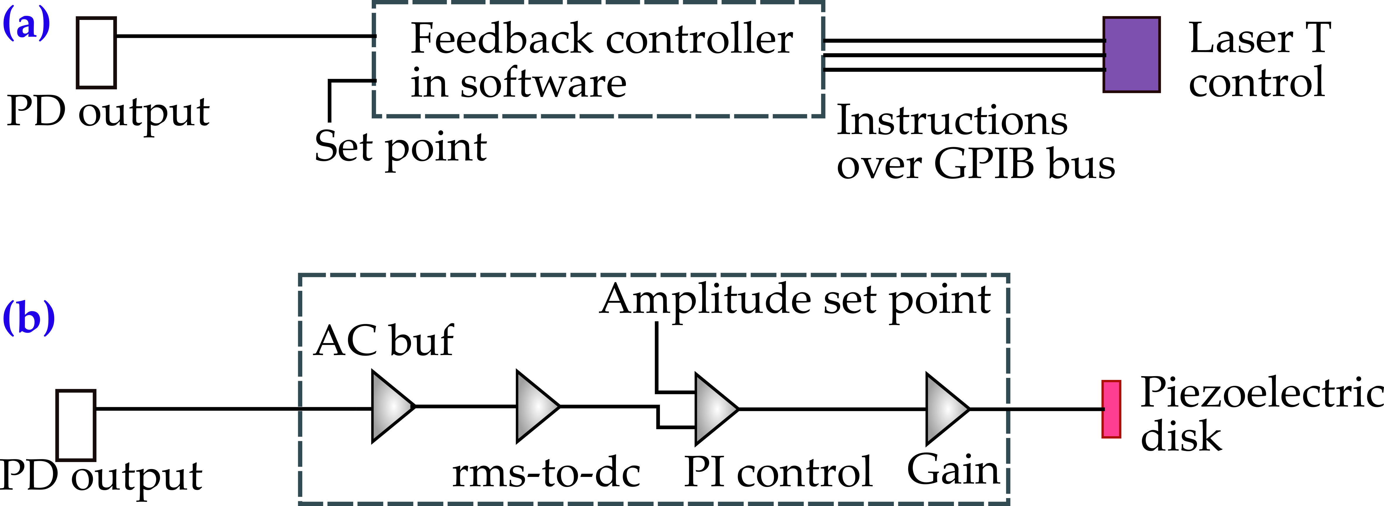 Figure 3: Implementation of the two feedback loops that are essential for the operation of the interferometer. (a) A control loop implemented in software keeps the interferometer operating at its most sensitive point. The photodetector output (PD output) is sampled by one channel of a digitizer and compared to a set point inside a software loop. The software loop corrects for any deviations from the set point by sending instructions to slightly change the laser temperature which in turn changes its wavelength. With a 3 mm cavity, even slight changes in the laser temperature are sufficient to keep the interferometer at its operating point. (b) A second control loop runs in hardware and is used to maintain the amplitude of the mirror vibrations at a constant level. The same PD output is furnished to the ac coupled input buffer of our analog controller. The buffer feeds the rms-to-dc converter which supplies the two stage PI control amplifiers with a dc signal. The dc signal is compared to the amplitude set point, an error signal is generated and amplified, and which is then sent to the piezoelectric disk.
Results
The thermally driven vibrations of the silicon mirror were passively monitored by our interferometer. For this, the silicon mirror was placed inside the vacuum chamber evacuated to a base pressure of roughly 10-6 Torr. The interferometer was fringe locked with the dc feedback loop enabled, and the detector output was sampled by a fast digitizing board and saved into a deep onboard buffer. This data buffer was transferred periodically to a PC, Fourier transformed and plotted in quasi real time to visualize the spectrum of amplitude vibrations in frequency space.
A typical frequency spectrum is shown in Figure 4 below. A peak in the spectrum at roughly 6055 Hz is the natural resonant frequency of the mirror and the peak amplitude fluctuations reach a spectral density of almost 1 nm at room temperature. Away from resonance, the interferometer output is dominated not by the ampitude noise of the mirror vibrations, but rather the noise floor of the interferometer itself. We estimate this to be roughly
2 picometers per root Hz at about 6 kHz which is a measure of how sensitive our interferometer is to small changes in the length of the cavity, provided those changes occur at 6 kHz. At lower frequencies, the noise floor degrades and is significantly worse.
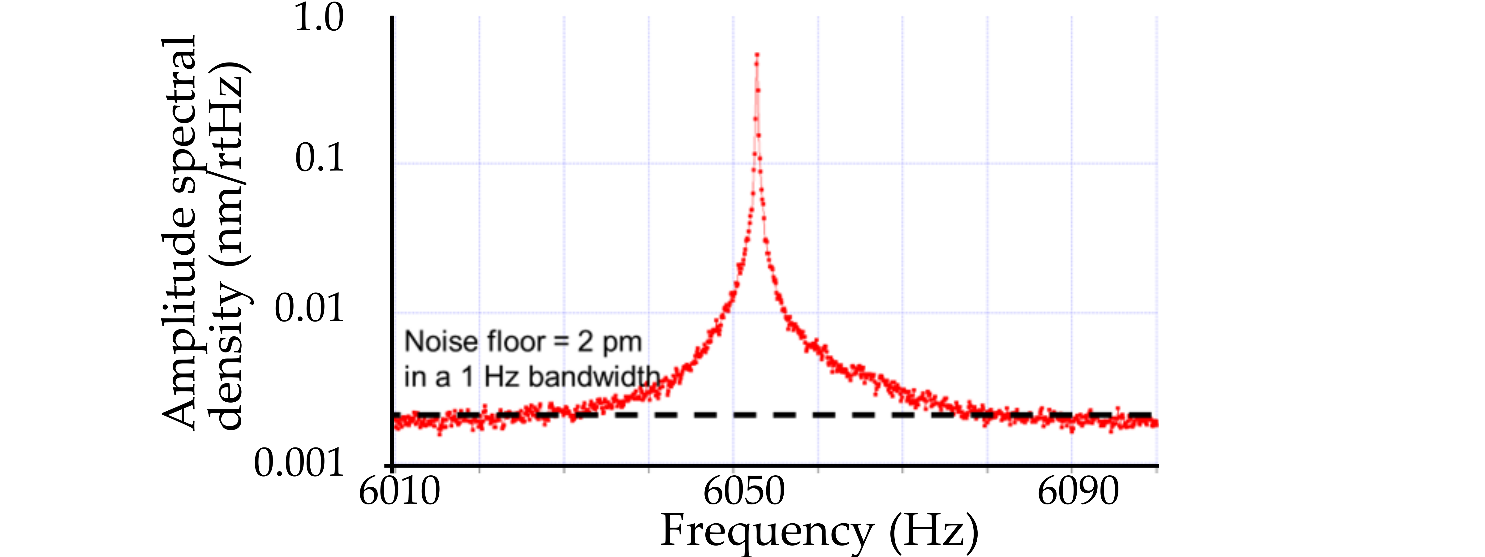
Figure 4: Thermally driven vibrations of a silicon mirror passively monitored by our interferometer. The mirror was placed in a vacuum chamber and evacuated to to base pressure of roughly 10-6 Torr. The interferometer noise floor is estimated to be about 2 picometers per root Hz at about 6 kHz.  Skip to main content
